Home » Without Label » Contrl Wiring Diagram Of Star Delta Starter / Star-delta motor starter explained in details - ELECTRICAL ... - Star delta starter control circuit wiring diagram consist timer, push button for start and stop.
Contrl Wiring Diagram Of Star Delta Starter / Star-delta motor starter explained in details - ELECTRICAL ... - Star delta starter control circuit wiring diagram consist timer, push button for start and stop.
Contrl Wiring Diagram Of Star Delta Starter / Star-delta motor starter explained in details - ELECTRICAL ... - Star delta starter control circuit wiring diagram consist timer, push button for start and stop.. Star delta starter y starter capacity control wiring. Star delta motor starter explained in details eep madcomics manual circuit diagram plain english electrical4u wye starters working the engineering mindset control wiring connection advantages included using with diagrams turbofuture automatic for motors star delta motor starter explained in details eep madcomics manual star delta starter circuit diagram star delta motor starter explained in. In control wiring diagram all magnetic contactors coils are rated 220 vac. The control circuit uses to control the starter circuit such as on, off and tripping operations. As and when motor attains good rotational speed, say about 90% of full r.p.m after few seconds, timer connected in starter disconnects star contactor first and then connects delta contactor.
In the above star delta starter control circuit wiring diagram with timer and normally close push buttonnormally open push button switch. In star delta starting an induction motor is connected i. Star delta connection circuit diagram: Connect those all terminal with the motor as shown in the above diagram. In star connected state, voltage applied is reduced to 1/√3 of the line voltage across each winding.
Star-Delta Wiring Diagram - Electrical Engineering Updates ... from i.pinimg.com Power and #control circuit.star delta starter control circuit #diagram star delta control circuit s. Motor control panel wiring diagram pdf star delta starter electrical notes articles is one of the pictures that are related to the picture before in the collection gallery, uploaded by autocardesign.org.you can also look for some pictures that related to wiring diagram by scroll down to collection on below this picture. Star delta starter wiring diagram, this post is about the main wiring connection of three phase motor with star delta starter and control wiring diagram of 1 mccb circuit breaker 3 magnetic contactors 3 phase motor thermal overload relay / electronic overload relay ocr an on daily timer (8 pin timer. In control wiring diagram all magnetic contactors coils are rated 220 vac. In star delta starting an induction motor is connected i. In the control wiring diagram, all magnetic contactors coils are rated 220 vac. The control circuit uses to control the starter circuit such as on, off and tripping operations. Between these two, star connected and delta connected states, circuit becomes open and motor neither.
Star delta starter y starter capacity control wiring.
As and when motor attains good rotational speed, say about 90% of full r.p.m after few seconds, timer connected in starter disconnects star contactor first and then connects delta contactor. The control circuit uses to control the starter circuit such as on, off and tripping operations. Star delta starter control wiring. A wiring diagram usually gives opinion just about the relative point and concord of. Star delta starter design normally consists of three contactors, an overload relay and a timer for for star delta starter circuit diagram,wiring technique and motor base termination,please read my post for star delta motor connection.also for simple star delta control circuit wiring and types of star. R , y, b = red, yellow, blue ( 3 phase lines)c.b = general circuit breakermain = mai supplyy = starδ = deltac1, c2, c3 = contatcors (power diagram)o/l = over load relayno = normally opennc = normally closed k1 = contactor (contactor coil) k1/no = contactor holding coil. As you see in the above star delta starter diagram, first, an nc push button switch is connected to stop the operation. One is power circuit and another one is control circuit. Connect those all terminal with the motor as shown in the above diagram. This energized star contactor coil and motor get connected in star. The on delay timer diagram is also shown in the diagram. And their applications with advantages. Power and #control circuit.star delta starter control circuit #diagram star delta control circuit s.
Next, the circuit goes through the nc terminals of the thermal over load relay. Here you can see the control circuit diagram of automatic star delta starter. Star delta connection circuit diagram: In star connected state, voltage applied is reduced to 1/√3 of the line voltage across each winding. Connect those all terminal with the motor as shown in the above diagram.
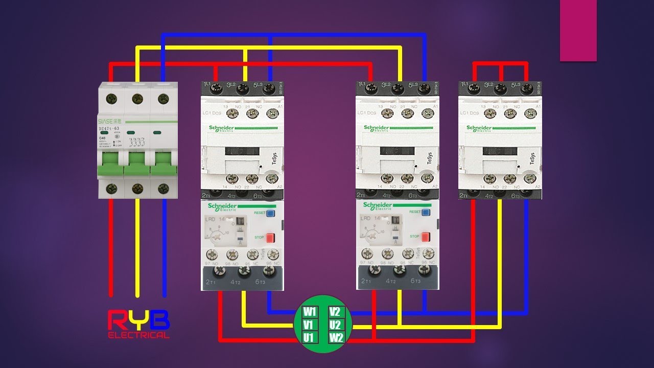
Star delta starter power circuit wiring diagram - YouTube from i.ytimg.com As you see in the above star delta starter diagram, first, an nc push button switch is connected to stop the operation. One is power circuit and another one is control circuit. Here you can see the control circuit diagram of automatic star delta starter. Automatic star delta starter with timer for 3 phase ac motors in this tutorial we will enactment the star delta y 3 phase induction ac motor starting method by automatic star delta starter subsequently timer subsequent to schematic facility control and wiring diagram as competently as how star delta starter works and their applications in. Star delta starter control circuit diagram. Star delta starter control circuit wiring diagram consist timer, push button for start and stop. Drawings explained step by step. In the above star delta starter control circuit wiring diagram with timer and normally close push button/normally open push button switch.
In the control wiring diagram, all magnetic contactors coils are rated 220 vac.
Star delta starter wiring diagram, this post is about the main wiring connection of three phase motor with star delta starter and control wiring diagram of 1 mccb circuit breaker 3 magnetic contactors 3 phase motor thermal overload relay / electronic overload relay ocr an on daily timer (8 pin timer. In the above star delta starter control circuit wiring diagram with timer and normally close push buttonnormally open push button switch. A 8 pin timer is used. Motor control panel wiring diagram pdf star delta starter electrical notes articles is one of the pictures that are related to the picture before in the collection gallery, uploaded by autocardesign.org.you can also look for some pictures that related to wiring diagram by scroll down to collection on below this picture. Refer to the below star delta circuit, A star delta starter is the most commonly used method for the starting of a 3 phase induction motor. Between these two, star connected and delta connected states, circuit becomes open and motor neither. Now, you have a total of six terminals to connect with the motor three from the output of the olr and three from the output of the delta contactor. Star delta starter control wiring. And their applications with advantages. Star delta motor starter explained in details eep madcomics manual circuit diagram plain english electrical4u wye starters working the engineering mindset control wiring connection advantages included using with diagrams turbofuture automatic for motors star delta motor starter explained in details eep madcomics manual star delta starter circuit diagram star delta motor starter explained in. This energized star contactor coil and motor get connected in star. Automatic star delta starter with timer for 3 phase ac motors in this tutorial we will enactment the star delta y 3 phase induction ac motor starting method by automatic star delta starter subsequently timer subsequent to schematic facility control and wiring diagram as competently as how star delta starter works and their applications in.
A wiring diagram usually gives opinion just about the relative point and concord of. Star delta starters consist of a power circuit and control circuit. Next, the circuit goes through the nc terminals of the thermal over load relay. More electrical tips and diagrams www.aboutelectricit. Between these two, star connected and delta connected states, circuit becomes open and motor neither.
Star Delta Starter Simple Circuit Diagram - Sexy Fucking ... from 1.bp.blogspot.com R , y, b = red, yellow, blue ( 3 phase lines)c.b = general circuit breakermain = mai supplyy = starδ = deltac1, c2, c3 = contatcors (power diagram)o/l = over load relayno = normally opennc = normally closed k1 = contactor (contactor coil) k1/no = contactor holding coil. A 8 pin timer are used. Star delta motor starter explained in details eep madcomics manual circuit diagram plain english electrical4u wye starters working the engineering mindset control wiring connection advantages included using with diagrams turbofuture automatic for motors star delta motor starter explained in details eep madcomics manual star delta starter circuit diagram star delta motor starter explained in. Drawings explained step by step. Motor control panel wiring diagram pdf star delta starter electrical notes articles is one of the pictures that are related to the picture before in the collection gallery, uploaded by autocardesign.org.you can also look for some pictures that related to wiring diagram by scroll down to collection on below this picture. As shown in the fig. Connect those all terminal with the motor as shown in the above diagram. One is power circuit and another one is control circuit.
Refer to the below star delta circuit,
Here you can see the control circuit diagram of automatic star delta starter. The control circuit uses to control the starter circuit such as on, off and tripping operations. In control wiring diagram all magnetic contactors coils are rated 220 vac. A 8 pin timer is used. A star delta starter is the most commonly used method for the starting of a 3 phase induction motor. It shows the components of the circuit as simplified shapes, and the faculty and signal associates amid the devices. Star delta starters consist of a power circuit and control circuit. Power and #control circuit.star delta starter control circuit #diagram star delta control circuit s. In the control wiring diagram, all magnetic contactors coils are rated 220 vac. In star connected state, voltage applied is reduced to 1/√3 of the line voltage across each winding. Now, you have a total of six terminals to connect with the motor three from the output of the olr and three from the output of the delta contactor. As shown in the fig. The on delay timer diagram is also shown in the diagram.